
📚 Technical Knowledge Base

MIM & CIM Technical Insights & Engineering Articles

Industry knowledge, DFM guidelines, material selection whitepapers, and precision powder metallurgy case studies from MIM Supplier.

🔬 Advanced Ceramics & Metallurgy

Precision Ceramic & Metal Molding Innovations

Deep dive into micro-molding tolerances, debinding-sintering processes, and high-purity ceramic solutions for global OEMs.

⚙️ Medical, Optical & Auto Guides

Design for Manufacturability Best Practices

Practical engineering insights on optimizing part geometries, reducing tooling costs, and achieving 1µm tolerances.

0%

Precision MIM Optical Instrument Parts help manufacturers create compact components with intricate forms and consistent dimensions. Metal injection molding combines fine metal powders with a binder, followed by debinding and sintering. The process can support features that are difficult to machine economically, including thin walls, small slots, and curved mounting details. Precision still depends on disciplined process control. A tiny dimensional shift can affect alignment inside a lens barrel or sensor housing.

Supplier choice matters. Strong candidates explain their material options, tooling approach, inspection methods, and production limits in plain terms. Ask how they manage shrinkage, surface finish, and critical dimensions. Request sample parts and measurement reports. A polished brochure is not proof. Neither is a low quote.

Powder-metallurgy authority Randall M. German has written extensively about powder injection molding. In paraphrase, his work highlights a useful principle: complex shapes become valuable when the process can reproduce them reliably. That is the standard behind this guide to Top Precision MIM Optical Instrument Parts Suppliers. Look for evidence, not promises. A supplier should discuss where MIM fits—and where it may not. That honest boundary is easy to overlook. It deserves attention.
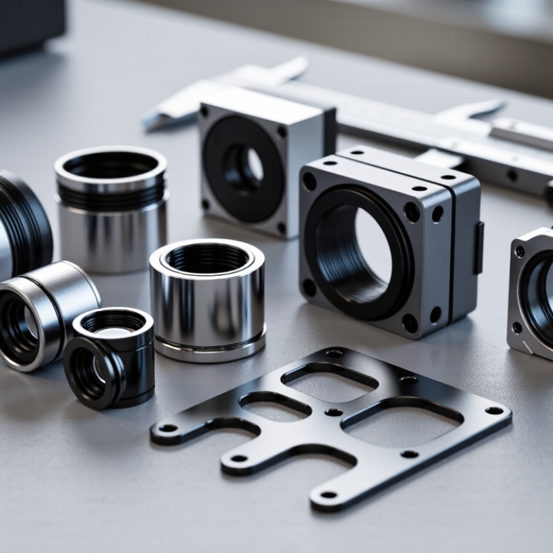
Top Precision MIM Optical Instrument Parts Suppliers

Understanding Metal Injection Molding for Optical Instrument Parts

Understanding Metal Injection Molding for Optical Instrument Parts

Metal injection molding (MIM) combines fine metal powder with a binder to form feedstock. The feedstock is injected into a mold, then debound and sintered. This process can produce small, intricate components such as lens-barrel retainers, adjustment rings, and sensor housings. Geometry matters. So do stable datums and repeatable fits. MIM can shape complex parts, but critical optical surfaces may still need precision machining, grinding, or polishing.

Grand View Research’s 2024 Metal Injection Molding Market analysis estimated the global market at USD 4.2 billion in 2023, with projected growth of 11.9% annually through 2030. This figure covers MIM broadly, not optical parts alone. It signals expanding process adoption, not guaranteed savings for every design. MIM is not automatically the cheaper choice. Tooling, production volume, material selection, and finishing needs all affect cost. The uncomfortable detail: a tiny alignment error can outweigh an impressive-looking production quote.

Tips: Share drawings with a MIM supplier early. Identify optical interfaces, tolerances, and surfaces that cannot be altered. Ask for sample parts and measurement data before approving production. Check shrinkage allowances, too. They deserve careful review.

Optical Components Commonly Made with Precision MIM

Optical instruments use many small metal parts that guide movement rather than transmit light. Precision metal injection molding (MIM) can produce lens-retaining rings, focus and zoom cam components, miniature gears, sensor brackets, and shutter linkages. These parts often need thin walls, detailed features, and repeatable fit inside compact assemblies. The lenses themselves are generally made from glass or optical polymers, not MIM metal. That distinction matters.

A 2024 Grand View Research report estimates the global MIM market reached USD 4.06 billion in 2023, with a projected 7.4% compound annual growth rate from 2024 to 2030. This growth reflects demand for small, complex metal components across several industries, including optical equipment. For instrument makers, MIM can reduce machining steps when a part has intricate geometry and suitable production volumes. But it is not automatically the best route. Sintering shrinkage must be controlled, and critical bores or locating faces may still need secondary machining. A cam ring may look simple on a drawing; its motion can feel rough if clearances drift. The practical choice depends on material, tolerance, surface requirements, and inspection capability. Details matter.

Top Precision MIM Optical Instrument Parts Suppliers - Optical Components Commonly Made with Precision MIM

Component type Typical function Why consider MIM Potential material options Design and finishing considerations
Lens retaining rings Secure lenses or filter elements within an optical assembly. Can form compact rings with features such as slots, shoulders, or external grip details. 316L stainless steel; 17-4 PH stainless steel Machine critical seating faces and threads when the required fit or alignment cannot be achieved directly by molding.
Lens-barrel spacers and internal sleeves Maintain spacing between optical elements or support components inside a barrel. MIM can consolidate small parts with internal steps or other non-simple geometry. 316L stainless steel; 17-4 PH stainless steel Specify post-machining for precision bores, perpendicular faces, and optical alignment datums as needed.
Aperture plates and stops Limit the light path to control stray light or define an optical aperture. Suitable for small parts that combine an opening with mounting or locating features. 316L stainless steel; 17-4 PH stainless steel Aperture size, edge quality, flatness, and surface reflectivity may require secondary machining or a specified surface treatment.
Optical module housings and small carriers Support or locate lenses, sensors, filters, and related hardware. MIM is useful for compact housings with integrated ribs, bosses, and mounting features. 316L stainless steel; 17-4 PH stainless steel Review shrinkage, wall thickness, and datum strategy with the MIM manufacturer; finish critical locating surfaces if required.
Mounting brackets and alignment supports Attach optical subassemblies to instrument frames and help maintain their position. Complex shapes and multiple mounting features can often be formed in one part. 17-4 PH stainless steel; 316L stainless steel Use machined datums where alignment, flatness, or hole-position requirements are demanding.
Adjustment knobs and small control components Provide user-operated control of focus, position, or instrument settings. MIM can produce compact forms with grip features, recesses, and integrated attachment details. 316L stainless steel; 17-4 PH stainless steel Check the fit of shafts, inserts, and threads; deburring or surface finishing may be needed for handling comfort.
Small linkages and shutter mechanisms Transfer motion in compact instrument mechanisms, including some shutter or actuator assemblies. Can suit small, intricate metal parts when production volumes and geometry support MIM economics. 17-4 PH stainless steel; 316L stainless steel Validate strength, wear, fatigue, and moving clearances for the specific mechanism; precision pivot features may need machining.

Note: MIM suitability depends on part geometry, material, production volume, and required tolerances. Optical-quality lens surfaces are not produced by MIM; critical bores, threads, seating faces, and alignment features commonly require secondary machining or finishing.

Precision and Quality Requirements for MIM Optical Parts

MIM optical instrument parts often sit beside lenses, sensors, or moving assemblies, where small dimensional shifts can affect alignment. Precision starts with a clear drawing: critical datums, fit surfaces, wall thickness, and allowable variation should be identified before tooling begins. A supplier should explain how powder selection, feedstock preparation, molding, debinding, and sintering influence the finished geometry. Shrinkage is expected, but it must be measured and compensated for, not treated as a surprise. Small errors matter.

Surface condition deserves equal attention. A rough or porous interface may complicate cleaning, coating, or assembly, even when the part meets its basic dimensions. Inspection plans can combine calibrated dimensional checks with visual review and, where appropriate, density or material tests. Sample parts should be evaluated in the actual assembly, because a gauge alone cannot reveal every fit issue.

No process is perfect.

I would not call a component ready just because its dimensions pass; the inspection method and measurement uncertainty also need review. Clear records of material lots, process settings, and inspection results make quality easier to verify and repeat across production batches.

How Leading Suppliers Manufacture and Inspect MIM Components

Precision MIM suppliers make optical instrument parts such as miniature brackets, sensor housings, and alignment frames. These components support optical systems; they rarely replace polished lens surfaces. Production starts with metal powder and binder, mixed into feedstock and injected into precision tooling. Debinding removes most of the binder, then controlled sintering densifies the part. Small details matter. Gate position, furnace uniformity, and shrinkage can shift a mounting feature by microns. The Metal Powder Industries Federation’s MIM design guidance places typical dimensional capability near ±0.3% of a feature, subject to geometry and process controls. That is a guide, not a promise.

Inspection should follow the features that affect assembly. Suppliers commonly use coordinate measuring machines for hole position and flatness, optical comparators for profiles, and surface instruments for finish. CT scanning can reveal internal voids, but it does not replace dimensional checks. A useful inspection plan links each critical drawing tolerance to a measurement method and a recorded result. Grand View Research estimated the global MIM market at about US$4.6 billion in 2023, reflecting broad industrial use rather than optical applications alone. Batch traceability matters. Yet inspection can still miss a weak point: measurements taken before final cleaning may not represent the part as assembled. Teams should review sampling frequency and measurement uncertainty with customers, then adjust controls when actual assembly data disagrees.

How to Evaluate Precision MIM Optical Instrument Parts Suppliers

Top Precision MIM Optical Instrument Parts Suppliers

How to Evaluate Precision MIM Optical Instrument Parts Suppliers

Evaluate suppliers by checking whether their process controls match your part’s actual function. For a camera housing or sensor bracket, inspect the datum surfaces, thin walls, threaded features, and interfaces with lenses or other optical components. The Metal Powder Industries Federation’s Metal Injection Molding Design Guide cites typical as-sintered tolerances of about ±0.3% to ±0.5% of a dimension. This is a design reference, not a guarantee; geometry, material, and sintering conditions affect results. That matters. Ask suppliers to show dimensional reports from production batches, not only a polished sample. Confirm their measurement equipment is calibrated and appropriate for small features.

Check material certificates, process records, and how the supplier handles changes to feedstock, tooling, or furnace settings. For critical fits, request capability data for the dimensions that affect alignment and assembly. Ask how defects such as distortion, porosity, or surface variation are detected. A supplier may provide attractive prototypes yet struggle to repeat them at production volume. No process is perfect; look for clear limits and corrective actions, rather than broad promises.

Tips: Send a controlled drawing and a representative assembly sample. Request a first-article inspection report, sample size, measurement method, and tolerance exceptions. Compare lead time and quoted cost only after confirming the technical evidence.

FAQS

What is metal injection molding?

It mixes fine metal powder with a binder, injects the feedstock into a mold, then removes the binder and sinters the part.

Which optical instrument parts can MIM produce?

It can form small, intricate parts such as lens-barrel retainers, adjustment rings, sensor housings, and camera brackets.

Does MIM create finished optical surfaces?

Not always. Critical optical surfaces may still require machining, grinding, or polishing.

What tolerances can as-sintered MIM parts achieve?

A design guide cites typical tolerances around ±0.3% to ±0.5% of a dimension. Actual results depend on geometry, material, and sintering conditions.

What should I review before approving a part design?

Mark optical interfaces, datums, critical fits, and surfaces that must remain unchanged. Check shrinkage allowances carefully; a small alignment error can matter more than a low quote.

How can I check a supplier’s production consistency?

Request dimensional reports from production batches, not just a polished sample. Ask about calibrated measurement equipment, sample size, and inspection methods.

Which production records are worth requesting?

Review material certificates and process records. Ask how changes to feedstock, tooling, or furnace settings are controlled.

What defects should a supplier explain?

Ask how they detect distortion, porosity, and surface variation. Request capability data for dimensions that affect alignment and assembly.

Is MIM always less expensive than other methods?

No. Tooling, volume, material, and finishing needs all affect cost. I would still compare the technical evidence before trusting an attractive quote.

Conclusion

Precision MIM Optical Instrument Parts combine the design flexibility of metal injection molding with the dimensional consistency optical equipment demands. The process can form small, intricate components from metal powders and binders, then use debinding and sintering to achieve their final shape. Depending on the instrument design, MIM may be suitable for housings, mounts, adjustment parts, and other compact structural components. Each application calls for careful material and process selection to balance strength, stability, surface condition, and fit.

Reliable production depends on clearly defined tolerances and inspection criteria throughout manufacturing. Suppliers should be able to explain their tooling, process controls, measurement methods, and quality documentation, as well as how they manage samples and production changes. When evaluating a supplier, consider relevant technical experience, communication, consistency, and the ability to meet specified requirements. A thorough review helps ensure that MIM components integrate properly and perform dependably within optical assemblies.

Lucas

Lucas

Lucas is a dedicated marketing professional with extensive expertise in the industry, making him an invaluable asset to our team. With a keen understanding of our company’s products and services, he continually strives to elevate our brand through insightful and informative blog posts that reflect......