High-Precision Engineering
Metal Injection Molding (MIM) and Ceramic Injection Molding (CIM) require tooling of unmatched accuracy to compensate for linear debinding and sintering shrinkage (typically 15% to 22%). At MIM Supplier, our senior tooling engineers combine 15+ years of metallurgical expertise with advanced mold-flow simulation software to guarantee exact net-shape part geometry.
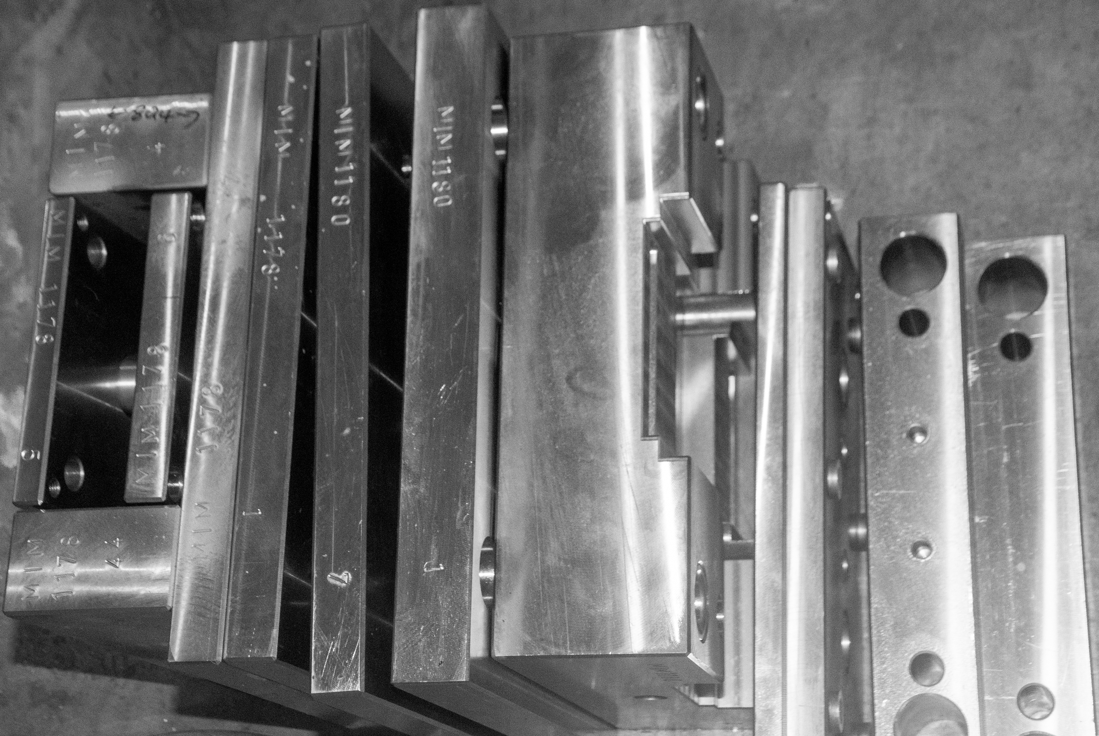
Every mold base is constructed from premium-grade hardened tool steel (S136, H13, P20, NAK80) and machined in-house using high-speed 5-axis CNC centers and mirror-finish EDM (Electrical Discharge Machining). Full metallographic inspection reports, dimensional CMM evaluation, and lifetime tooling warranties come standard with every production contract.
Tooling Standards & Technical Capabilities
Tooling Engineering Specifications
Our mold shop accommodates complex multi-cavity geometries, side-action sliders, unscrewing cores, and hot-runner systems customized for powder metallurgy.
| Specification Parameter |
Standard Tooling |
High-Precision OEM Grade |
| Mold Steel Materials |
P20, 718H, NAK80 |
S136 (HRC 48-52), H13 Vacuum Quenched, SKD61 |
| Dimensional Tolerance |
±0.010 mm |
±0.005 mm (Up to ±0.001 mm via CNC grinding) |
| Shrinkage Calculation Accuracy |
±0.15% Margin |
±0.03% (Verified via Computer-Aided DFM) |
| Guaranteed Mold Life |
300,000 Shots |
1,000,000+ Shots (Lifetime Warranty Offered) |
| Surface Finish (Polishing) |
Ra 0.4 µm (SPI B-1) |
Ra 0.01–0.05 µm (SPI A-1 Mirror Finish) |
| Mold Lead Time (Prototypes) |
7 – 12 Days |
10 – 18 Days (Includes Mold Trial T1 Samples) |
Engineering Workflow
5-Step Tooling Fabrication & Mold Verification
A rigorous technical workflow designed to eliminate defect risks before mass production starts.
Step 01
3D CAD Optimization & DFM Flow Analysis
Our engineers perform advanced Moldflow® computer simulations to evaluate gate placement, wall thickness uniformity, thermal dissipation, and green-state shrinkage behavior, preventing air traps or warping.
Step 02
Precision Mold Base Preparation
Standardized LKM/HASCO/DME mold bases are selected and heat-treated. Mold cores and cavities undergo stress-relieving cycles to guarantee long-term dimensional stability during continuous thermal cycles.
Step 03
High-Speed 5-Axis CNC Die Core Machining
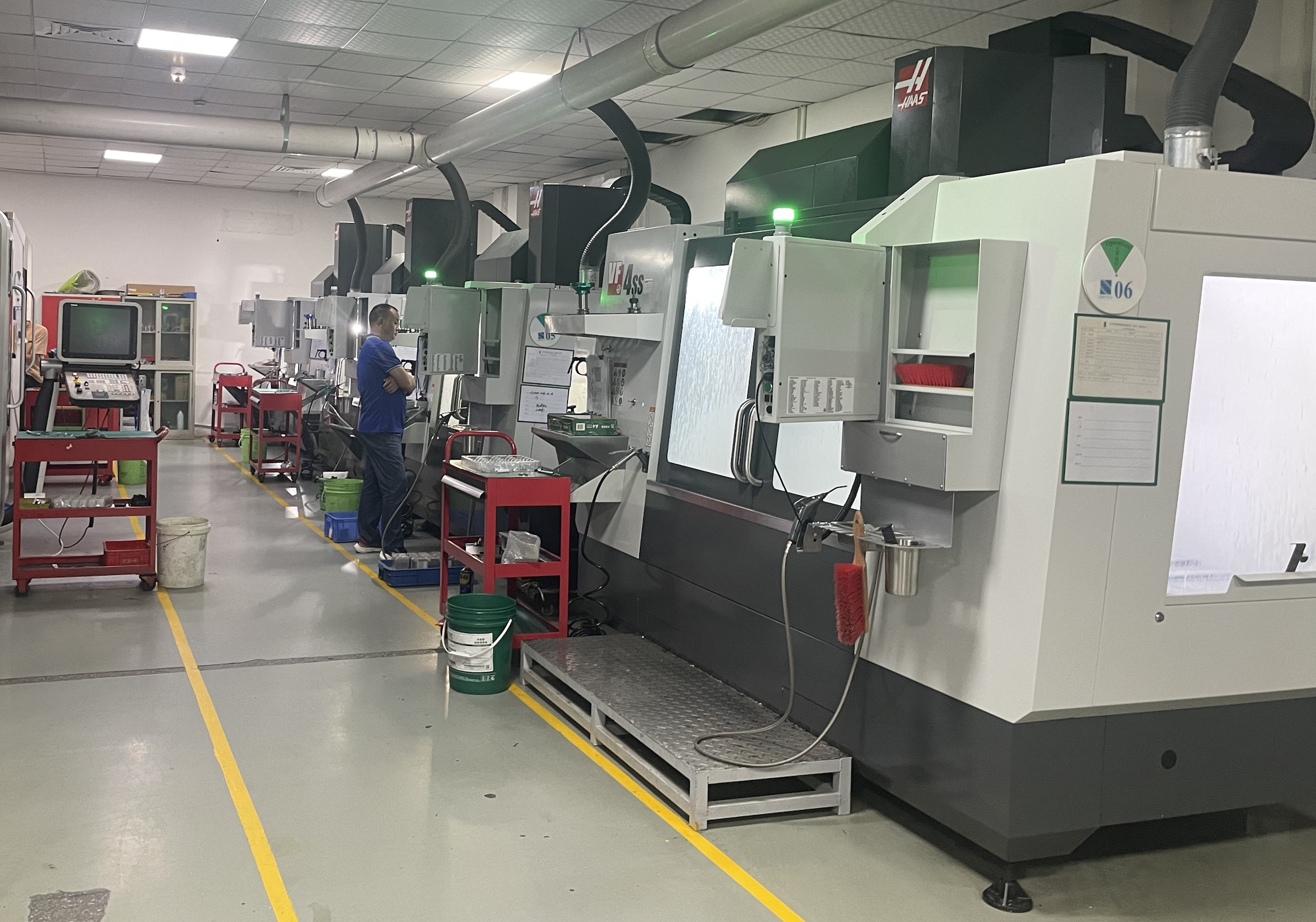
Die cores and intricate inserts are milled on 5-axis CNC machines operating at 24,000 RPM, achieving sub-micron accuracy for micro-features, thread inserts, and complex parting line contours.
Step 04
Electrical Discharge Machining (EDM & Wire EDM)
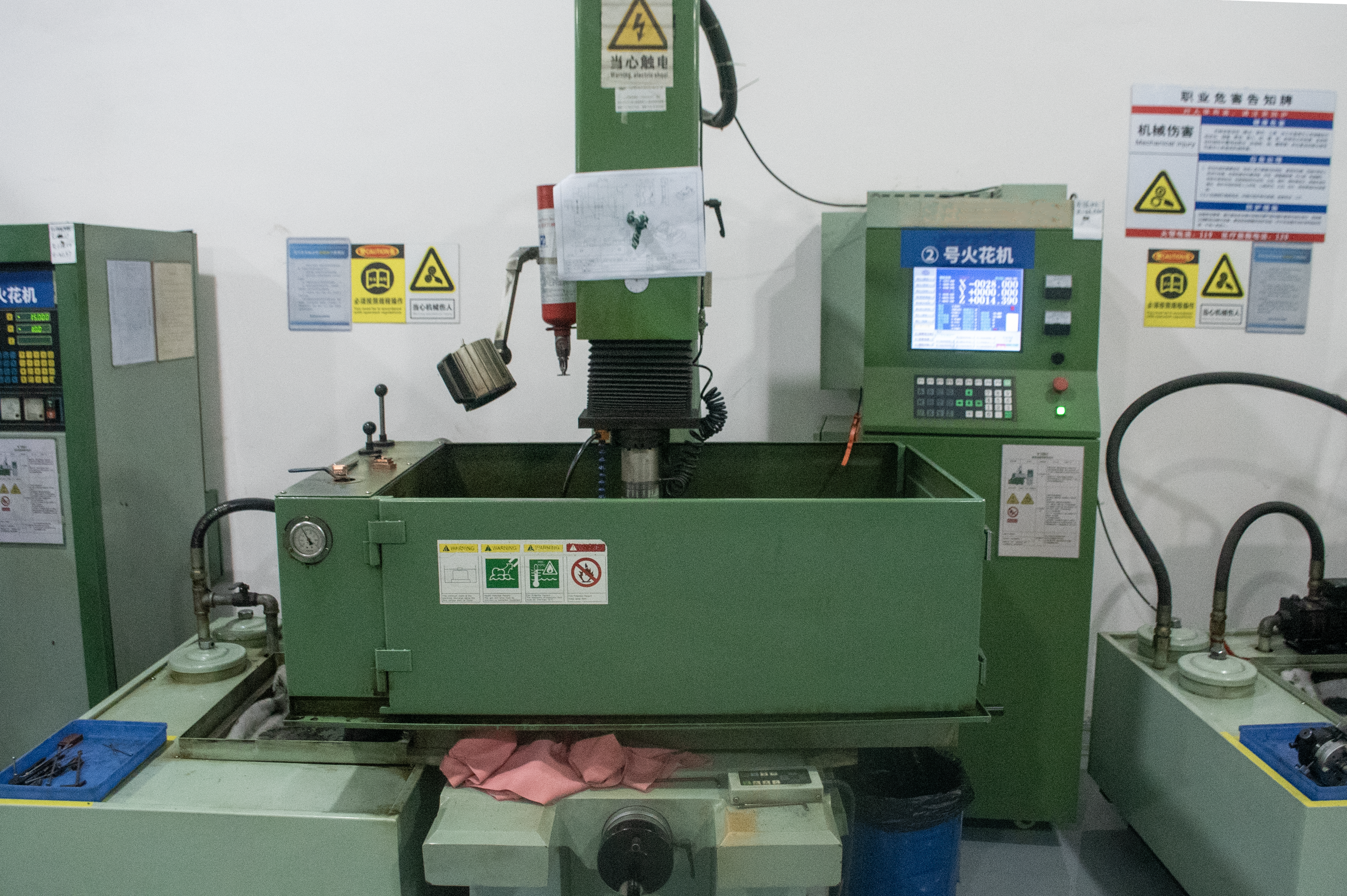
For sharp internal radii, narrow slots, and micro-grooves, CNC mirror EDM and Sodick Slow-Wire EDM machines generate pristine cavity textures without inducing mechanical stress on tool steel.
Step 05
Fitting, Polishing, Assembly & T1 Mold Trial
Experienced mold fitters hand-polish cavity surfaces up to SPI A-1 mirror grade, assemble ejector pin mechanisms, and run T1 injection trials. Sample parts undergo 100% CMM inspection prior to client approval.
Tooling Workshop & Machinery
In-House Toolroom Equipment & Inspection
Equipped with Japanese and European high-precision machinery to ensure optimal mold longevity and seamless repeatability.
Engineering Consultation
Frequently Asked Questions on MIM/CIM Tooling
Common technical questions answered by our lead tooling engineering staff.
How do you handle linear shrinkage compensation for MIM and CIM materials?
During powder injection molding, green parts shrink anywhere from 15% to 22% during debinding and sintering depending on powder loading density. Our tooling engineering team uses specialized CAD scaling formulas matched to raw material feedstock lots to calculate anisotropic shrinkage factors, guaranteeing accurate final dimensions.
What is the average lead time for a prototype MIM/CIM mold versus a mass production mold?
Single-cavity prototype molds (soft tooling or aluminum/P20 inserts) typically require 7 to 12 days. Hardened multi-cavity production tooling (S136 or H13 steel, HRC 48-52) requires 14 to 21 days, including T1 sample delivery and full CMM inspection documentation.
Do you offer lifetime mold maintenance and quality guarantees?
Yes. When production parts are manufactured in our facility, we take 100% responsibility for mold maintenance, storage, pin replacements, and cavity refurbishment at zero additional cost to our clients under our Lifetime Tooling Warranty.
What files are required to obtain a DFM analysis and tooling quotation?
Please provide 3D CAD models in STEP (.stp, .step), IGES (.igs), or Parasolid (.x_t) formats along with 2D technical drawings (PDF/DWG) specifying critical tolerances, surface finish (SPI grade), and alloy/ceramic material requirements.